Looking after your soldering iron
Without a clean soldering iron, you will always struggle to make a good joint.
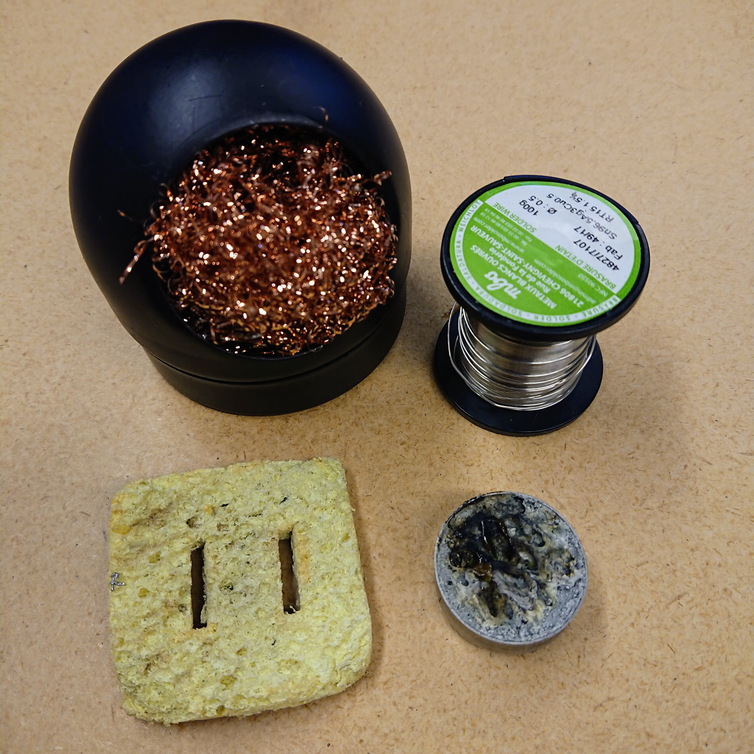
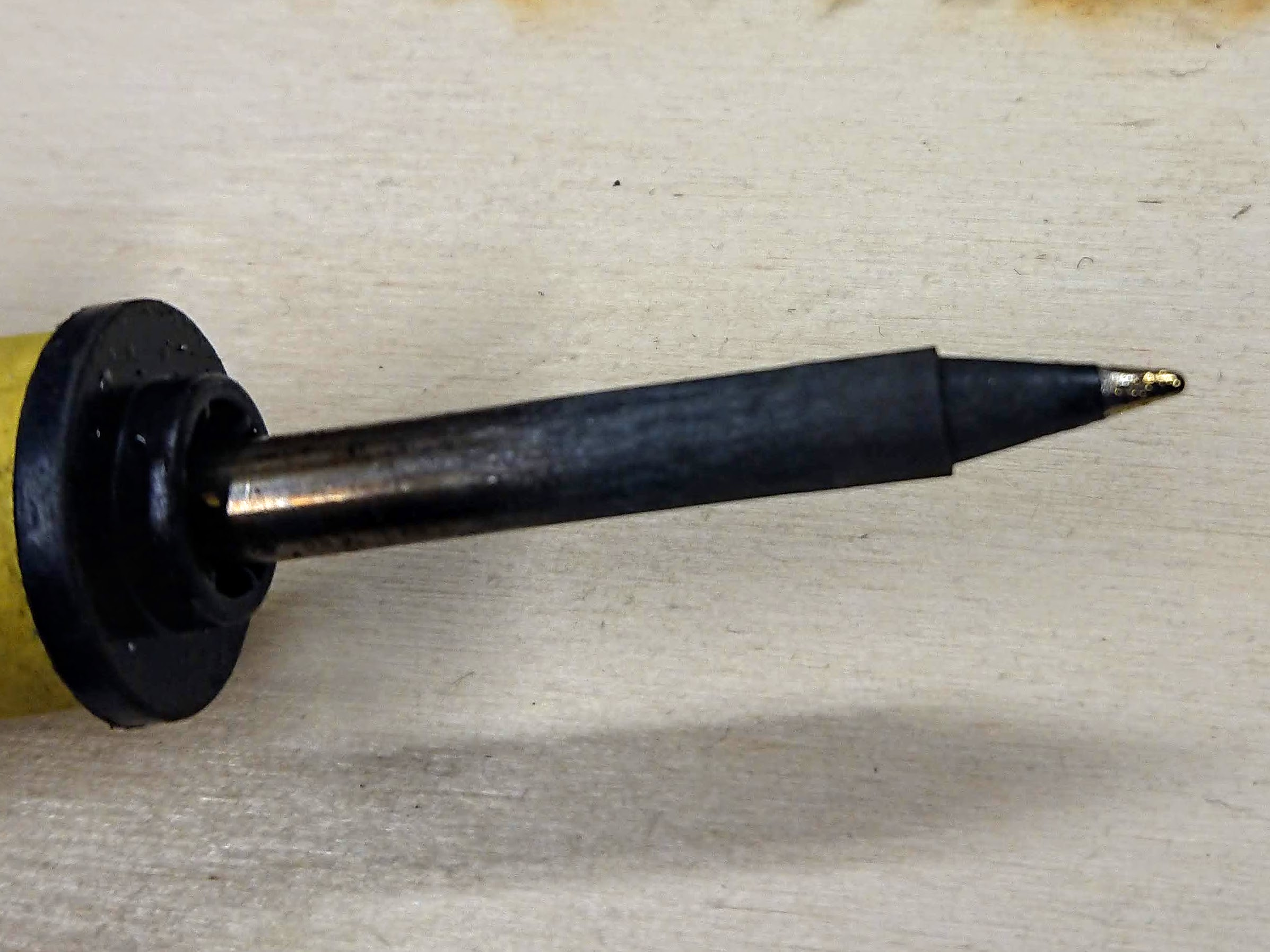
The tip of your iron, when hot, should be bright silver. If it is dull and brown, follow these steps to clean and tin it.
- Heat up your iron.
- Clean any deposits off the tip using brass wool or a wet sponge.
- Melt some solder onto the tip, then it clean off using your brass wool or sponge.
- The flux in the centre of your solder will clean the tip, and the solder itself will tin it.
- Repeat this process a couple of times if necessary, to get a bright tip.
- If this is not working, you can buy tip tinner or cleaner. This is a mixture of flux and solder, especially designed for this purpose.
- Push your hot iron into the paste, then wipe clean with your brass wool or sponge.
When you are finished, your iron's tip should be bright silver.
When you have finished soldering, repeat steps 2 and 3 before turning off your iron.
This will keep the iron clean, making it easier to use in the future.
Tips for making a good joint
Here a couple of guides to making a great solder joint:
- Kitronik's 'How to Solder', including clear close-up pictures.
- 'Soldering is Easy!' comic . There is also a shorter one-page version.
Deciphering a soldering kit
The workshop uses a LED soldering kit bought from AliExpress.
If you are not sure how to place all of your components correctly onto your board, this section will help you to identify all of the parts - both for this board and for future projects.
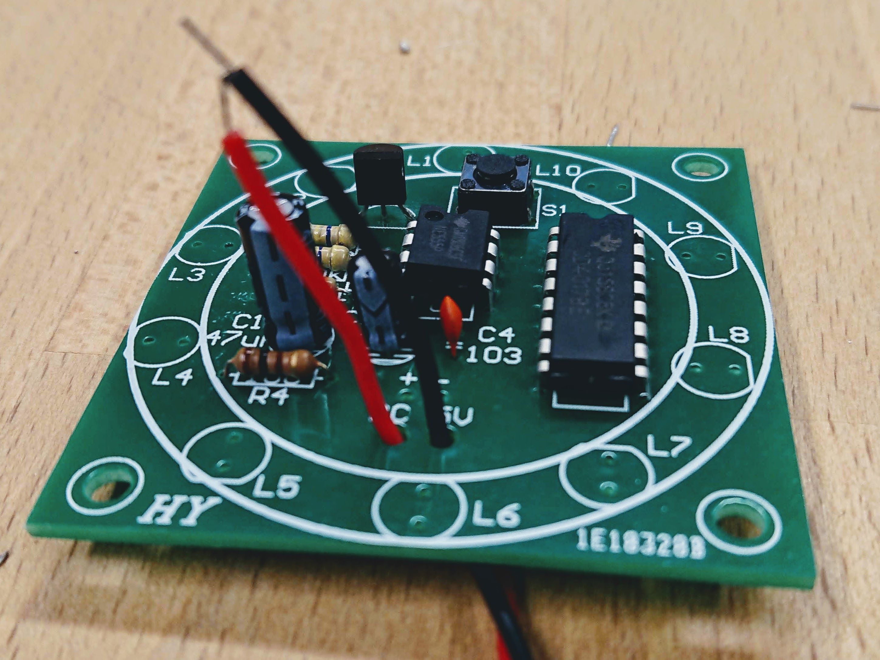
To skip straight to the final instructions, click here.The first step is matching all of your components to their space on the board. Lay out all of the components in front of you.
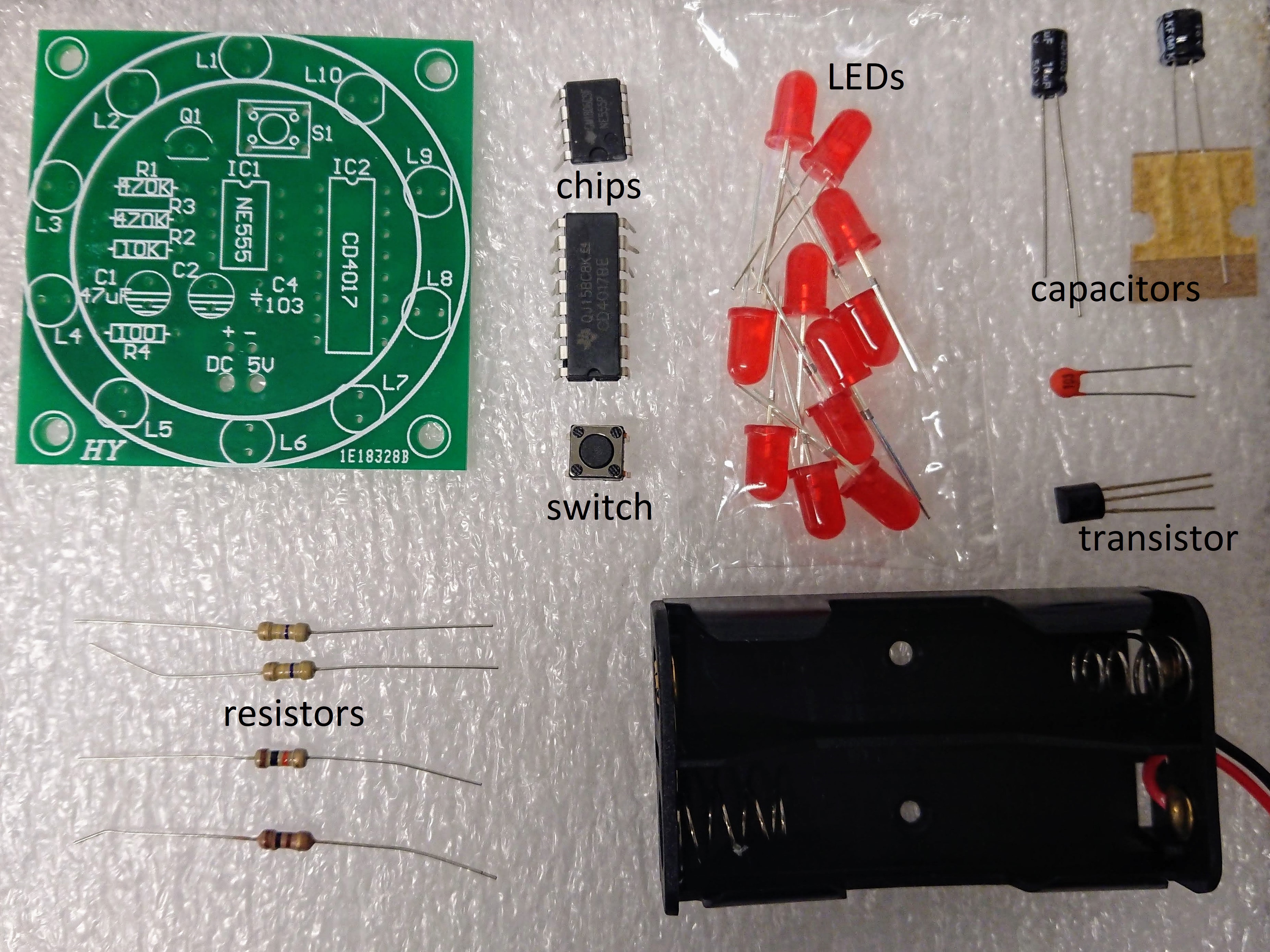
Even if you don't know what the components are, you can get a a good idea where most of the parts go by looking at the shape and size of them, as well as the number of parts.
For example:
Light emitting diodes (LEDs)
- There is a circle of ten component spaces around the edge of the board, all labelled L plus a number.
- You have at least ten LEDs in your kit (the red bulbs). Logically, these components should match, as there is nothing else suitable in your kit.
- LEDs have polarity - they will only work in one direction.
- Look carefully at one of the LEDs, the top is not a complete circle - one edge is flat. This edge matches up with the flat side of the drawings on the board.
- On other boards, LEDs could be labelled with a D for diode, or the electrical symbol for an LED.
Button switch
- You have a button switch, with four leads - there is only one place on the board this can go.
- Its orientation does not matter - it cannot fit in the board in an incorrect way.
- Its space is labelled S for switch.
Chips
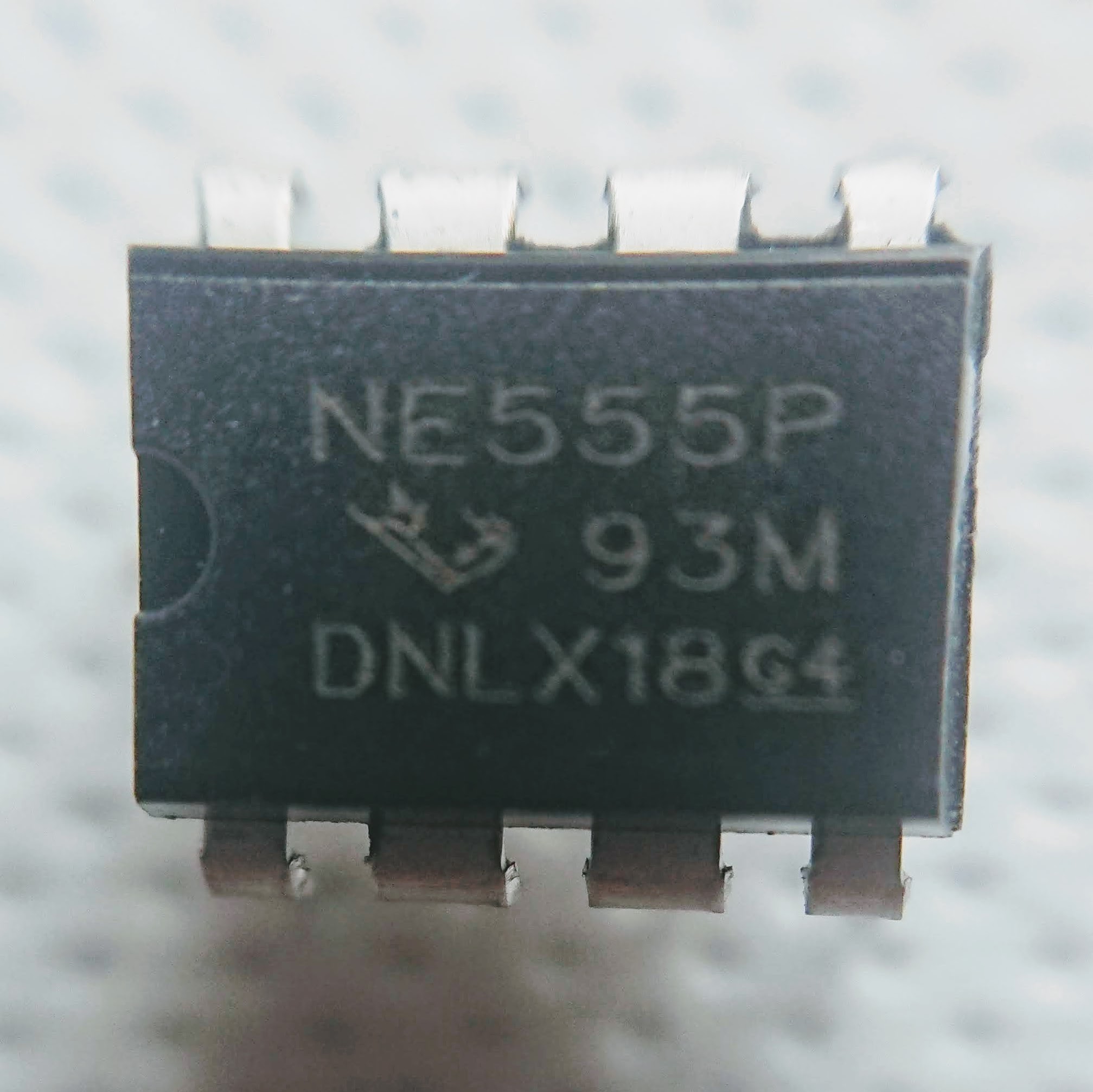
- You have two chips - a large one and a small one. They can both only fit on one location.
- These must be placed in the correct orientation.
- Look carefully at one of the chips - you should see a small dimple on the top.
- Match this dimple with the drawing on the board.
Capacitors
- You have three capacitors in your kit - two large blue ones, and one small orange one. There are three spaces labelled C on your board, but they all look slightly different.
- The small orange capacitor has the number 103 printed on it - find its space on the board. This capacitor is not polarised.
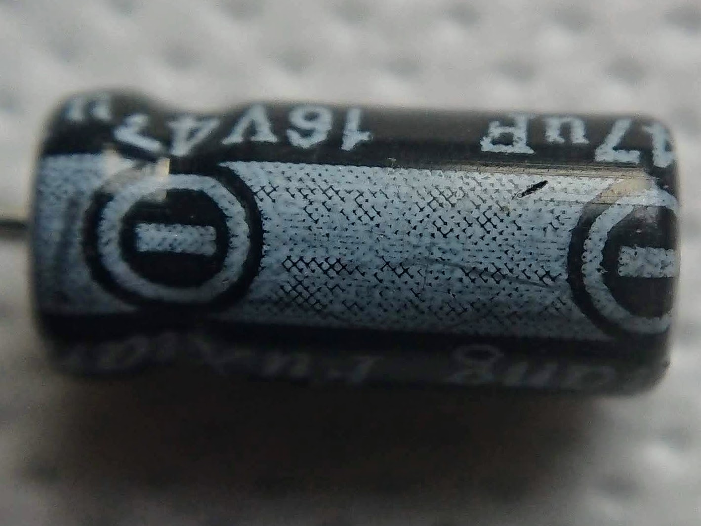
- There are two more spaces for capacitors on the board, one of them has a label 47uF - look carefully at your two capacitors to find the one labelled 47uF.
- These two capacitors are polarised. They have a stripe down one side to show the negative lead.
- This stripe matches the shaded side of the drawing on the board.
- Other boards may use the electrical symbol for a capacitor instead of a shaded drawing.
Transistor
- You have one component that has three legs. There is only one place for it to go!
- It matters which way around this component is placed - match its shape to the drawing on the board.
Resistors
- You have four resistors, and four spaces on the board labelled R.
- Two of the spaces are also labelled 470K, one labelled 10K and one 100.
- Look carefully at your four resistors - paying attention to the coloured bands. Two of them are identical, so must match with the two spaces labelled 470K.
- To work out the difference between your final two resistors, you need to use a resistor colour chart. Click here for one example.
Battery pack
- Find the holes on your board labelled + - and DC 5V.
- The black wire on your battery pack goes to the negative hole, the red wire to the positive hole.
- If you have four holes on the board, two larger than the other, then the two smaller holes are for soldering your wires to. The two larger holes are for pushing the wires through first, to help with stress relief so that the connection does not get pulled apart.
Key points
- If there is a drawing on the board indicating a shape - match it to your component, it will almost certainly not work in any other orientation.
- If there is no indication of which way around to place a component, it probably does not matter which way around it goes.
- If there is a number on the board, you will almost certainly have a component to match it.
- If you work out most of the components this way, you have less to google!
Soldering the PCB
A good habit to get into is starting from the shortest component, in this case the resistors. If you start with a tall component, you will be balancing the board awkwardly for the rest of the time!
Solder each component one at a time, then snip the leads down with wire cutters.
Following traces...
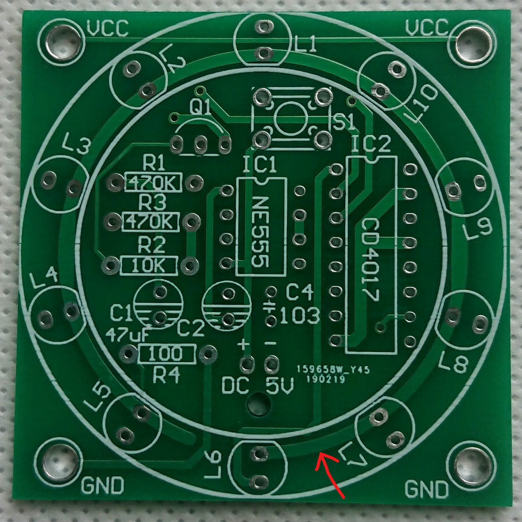
On one version of this board, the drawing to show the polarity of L6 is covered by other things.
To work out which way around it should go, look at the copper traces - these are the paler green lines.
If two holes are in the same patch of pale green, they are connected together.
The flat side of the LED is the negative side, and all of the negative sides will connect to ground, which means they all connect to the same place, therefore each other.
Look for the hole that the negative side of L5 or L7 will be soldered to, and see which pale green trace it is in. The L6 hole in the same trace, will be negative side of the LED.
Being able to decifer the traces on a board is a useful skill.
You can work out which components are connected together, and therefore more easily fix mistakes if you damage something during soldering.
Finishing up
When you have finished soldering, and snipped all of the wires, check that none of your joints are touching.
Put some batteries into your battery holder and see what happens - does it work?
If it is not working as expected, check all of your joints - do any look disconnected?
Remove your batterys, re-do any suspect joints, then replace your batteries.
Repeat until it works as expected!
Next steps
Cheap soldering kits are easy to get hold of from e.g. AliExpress or eBay.
Higher quality kits can be more useful once you've had some practice - you can make badges to wear, or something functional such as a battery tester.
Boldport kits are both beautiful and (sometimes) functional, and come with great documentation!